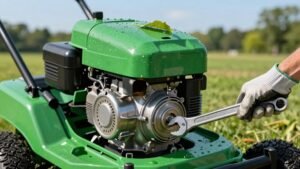

Pick a 12.5 HP Briggs & Stratton flathead, fit it to a right‑angle gearbox and centrifugal clutch, then reinforce the chassis with 3/4‑inch square‑tube bracing that ties the rear X‑brace to the front. Mount go‑kart spindles on a 24‑inch axle, set caster and camber, and align tie‑rods for precise steering. Install a 12‑tooth front sprocket, rear sprocket, and #35 chain, adding a disengageable belt clutch. Fit LMRA‑compliant rear brakes, a lightweight deck at least 4 inches above the frame, and route battery, wiring, and fuel lever per the schematic. Finally, tune ignition, fuel mixture, and blade alignment for peak performance; the next steps will reveal deeper adjustments.
Racing Lawn Mower: Choose Engine & Transmission
A solid foundation starts with the engine‑transmission combo, and most racers gravitate toward a 12.5 HP Briggs & Stratton flathead paired with a right‑angle gearbox and centrifugal clutch. You’ll select a flathead for its compactness, then apply engine tuning: shim the head down, bore the cylinder, port the intake, and install a larger carburetor to boost airflow. Upgrade to a billet aluminum connecting rod and a magnesium piston for higher RPM tolerance. For transmission upgrades, fit a right‑angle gearbox with an adjustable‑spring centrifugal clutch, then choose a go‑kart‑style clutch rated above stock horsepower. Add a second‑gear gear ratio for comfortable high‑speed cruising, and verify that the clutch springs are set for the desired engagement point. This systematic pairing maximizes power transfer while preserving durability. The new engine requires a modified exhaust to handle increased flow. Proper carburetor cleaning prevents fuel‑air mixture issues that can hinder performance.

For Gasket Set Fits For Briggs & Stratton 297615 397145 495603 5HP Horizontal Flathead

Fits Briggs & Stratton 5hp Flat Head Engine

Replace OEM Number: 398170 394228 390323 299169 170402 190432
Reinforce Frame & Align Front Axle for Racing Lawn Mower
When you reinforce the mower’s chassis and align the front axle, you eliminate the flex that turns a high‑speed run into a safety hazard. First, clamp a 3/4‑inch square steel tube to the rear X‑brace, then run it forward to the front brace using container welding for a seamless joint. Add a box‑tube or angle‑iron rail beneath the pan frame to tie front and rear sections together, preventing twist under cornering loads. Next, test flex by loading the front wheels and lifting the rear tire; note any inch‑scale deflection and reinforce those spots with additional tubing. Finally, align the front axle by welding two cross‑members and a central 3/4‑inch beam, then verify that the axle stays centered throughout lock range. Incorporate rear suspension upgrades if the design permits, ensuring the chassis remains rigid while the rear absorbs track bumps. This systematic approach yields a stiff, reliable platform for 40‑50 MPH racing. Rigid frame is essential to prevent twisting when driving over bumps. Proper soil aeration improves turf health and can be applied to the lawn surrounding the race track for better traction. Use a carpenter’s level to confirm the deck is perfectly level before each race. Regular core aeration also enhances soil structure, promoting deeper root growth and improved drainage.
Install Steering With Go‑Kart Spindles for Racing Lawn Mower
If you want a steering system that reacts instantly and holds its geometry under 40‑50 MPH, mount go‑kart spindles on the outside edges of the 24‑inch front axle and bolt them to the frame rails with C‑clips and retaining washers. Flip the axle, insert the spindle bolts, and secure both sides with retaining washers to prevent movement. Install the pitman arm on the center shaft, then thread tie rods from the shaft to each spindle, spacing them to achieve the desired Adjusting geometry. Set caster to stabilize at speed, then dial in the optimum camber settings—1.5° at straight ahead, 8‑9° at full lock—using the spindle’s built‑in camber adjustment. Finally, fine‑tune adjustingman geometry by moving tie‑rod attachment points until the inside tire turns sharply in curves while maintaining overall stability. Side rails are clamped to the frame for alignment before welding. Always wear protective gear when operating heavy equipment to reduce injury risk. Front‑wheel‑drive mowers provide tighter turning radii on uneven terrain, making them ideal for high‑traction handling.
Assemble Drivetrain: Chain, Sprockets, Clutch for Racing Lawn Mower
You’ll start by laying out the drivetrain architecture: a 12‑tooth front sprocket on a 5/8‑inch clutch shaft, a rear sprocket welded to the axle hub, and a #35 chain linking them, all driven by a disengageable belt clutch that meets class safety rules. First, verify sprocket sizing; the front 12‑tooth matches the #35 chain pitch, while the rear sprocket’s tooth count sets the final gear ratio. Weld the rear sprocket to the hub, ensuring a flat, clean joint. Install the belt clutch, aligning the idler pulley’s 3/8‑by‑16 TPI tapped center hole with the pivot bolt. Thread the chain, then perform chain tensioning using the adjustable idler arm, tightening until the chain deflects ≈ ½ inch under load. Torque all bolts to manufacturer specifications and double‑check that no protrusions violate safety limits. The clutch must be mounted on the opposite side of the belt‑taut side opposite side. Always wear protective gloves when handling sharp blades to prevent injury. Before beginning, make sure the mower is fully powered off and the spark plug is disconnected to avoid accidental start‑up. Remember to keep the mower’s center of gravity low while lifting to reduce strain and prevent tipping.

Applicable models: Compatible with 50cc 70cc 110cc 125cc 140cc 160cc ATV Dirt Bike Quad TaoTao Roketa Sunl

Made from SCM415 chromoly steel alloy
JT Sprockets JTF1901.12 12T Steel Front Sprocket , black , 12 Tooth
Mount Rear Brakes & Adjust Stopping Power for Racing Lawn Mower
Even before you tighten the final bolt, verify that the brake‑type you’ve chosen—hydraulic for its adjustability or mechanical for simplicity—fits the rear axle’s geometry and complies with safety clearances. Drill two mounting holes in the frame, use the existing chassis hole for the first caliper bolt, then add a second hole that clears pulleys and bearings. Align the caliper directly with the rotor; if the frame permits, skip a bracket. Mount the rotor on the axle’s keyway, slide it to the desired position, and lock it with set screws. Bolt the master cylinder through the frame, attach the three‑hole aluminum connector, and link the pedal rod with a bent 1/4‑inch steel rod. After assembly, bleed the system, adjust linkage tension, and test the parking brake to increase braking pressure and fine‑tune stopping power. The LED lights were tested and confirmed bright blue. Ensure the mower is on a stable surface and use a jack stand to support it securely before beginning any maintenance. Wear protective gloves to prevent cuts and bruises while handling sharp components.
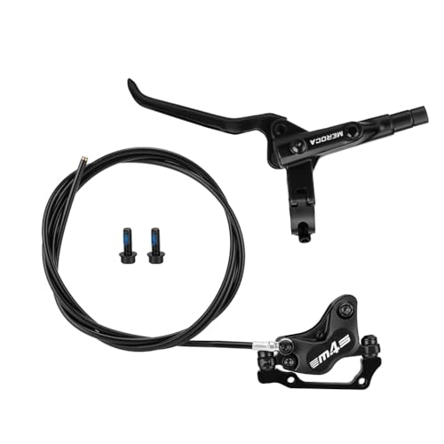
✔【Improved Braking Performance】The 4-piston bi-directional drive greatly enhances braking power, ensuring smooth and dependable stops while boosting safety across all riding conditions.

Hydraulic ATV Brake Kits fit for 50cc 70cc 90cc 110cc 125cc quad bike atv , most Chinese made atv, such as : TaoTao Buyang Coolsport Sunl Roketa AIM-EX etc
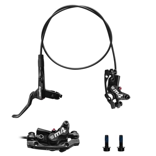
【4-Piston Hydraulic Brakes Precision】ZTZ 4 piston hydraulic brakes deliver 15% faster response vs standard hydraulic disc brakes, with 1.2m shorter stops at 30km/h. Safety Tip: Break-in pads with 10 gentle stops before aggressive use
Build Deck to Meet LMRA Height Limits for Racing Lawn Mower
Before you start cutting the deck, verify that its height and width comply with LMRA limits: the deck must sit at least 4 inches above the frame, not exceed the 2‑inch overhang beyond tire sidewalls, and stay within the 15‑inch maximum frame width. Measure the frame‑to‑deck clearance with a steel ruler; if it falls short, add shims or adjust mounting brackets for proper deck height adjustments. Choose suitable deck construction materials—lightweight aluminum or reinforced steel—to meet strength requirements while keeping weight low. Cut the deck to match the running‑board width, ensuring the edges align with tire sidewalls. Weld or bolt the halves securely, then re‑measure overhang and clearance. Confirm the final assembly stays within the 2‑inch overhang and 4‑inch minimum clearance before proceeding. Selecting the right blade type can dramatically improve cut quality on uneven terrain blade selection. Regularly inspect the blade for visible wear to maintain optimal cutting performance. Using a sharp cutting edge also reduces fuel consumption and promotes healthier grass growth.
Hook Up Battery, Wiring, and Fuel Lever for Racing Lawn Mower
Once the deck is verified and secured, install the battery directly behind the engine using the upward‑facing angle‑iron brackets, then pad it with rubber to protect the diamond‑plate floor. Verify a ¼‑inch clearance between the RAGB top and cover; this prevents interference during operation. Route the red wire through the directional diode, then to the solenoid’s battery side, and finally to the rear positive terminal, ensuring one‑way current flow for charging system optimization. Connect the orange alternator wire via its plug connector, keeping it isolated from the main harness. Bind the red and charging wires at the solenoid to share the positive line. Ground the black push‑button wire to the chassis and the green solenoid wire to battery negative. Observe all safety precautions while tightening connections. The engine‑side harness must be isolated from the chassis to prevent accidental short circuits. Before testing the battery, perform a visual inspection to confirm there are no cracks, corrosion, or loose terminals. Always check oil level after the engine has warmed up to ensure proper lubrication.

YTZ14S is a 12V 11.2AH 230 Cold Cranking Amps (CCA) Sealed Lead Acid (SLA) Battery

√ Dimensions: Length 7.68 inches, Width 5.12 inches, Height 6.22 inches, Total Height 7.09 inches; Weight: 21.5 lbs, Terminal Type: Square Hole Nut and Bolt, NB, Nut and Bolt, J; The positive terminal is on the left side of the battery; Cold Cranking Amps: 200CCA; Terminal: Left : Positive (+)-Red, Right: Negative (-)-Black.

ML-U1 is a 12V 200 Cold Cranking Amps (CCA) Sealed Lead Acid (SLA) Battery
Test, Tune, and Troubleshoot the Racing Lawn Mower Build
While you’ve secured the battery, wiring, and fuel lever, the next step is to verify that the engine runs correctly, fine‑tune the carburetor, and resolve any start‑up issues. Begin by removing the spark plug, turning the crank until a straw or pencil stalls, and confirming top dead center using the white timing lines. Reinstall the plug, then perform an ignition timing adjustment to guarantee proper advance. Check fuel tank capacity; fill with fresh treated fuel and confirm the carburetor is clear of clogs. Wind the mixture screw in until the engine stalls, then out until it runs smoothly, adding a slight extra turn. Observe exhaust color and sound, replace the air filter, and test the spark with a tester. If the mower won’t start, inspect battery voltage, PTO switch resistance, and compression, then clear any grass debris under the deck. Check engine timing with a timing light to ensure it matches the recommended specifications. Also, verify that the primer bulb is fully depressed before pulling the start cord to ensure fuel reaches the carburetor. Regularly inspect spark plug for wear or carbon buildup to maintain optimal ignition performance. Use a spark tester to confirm a strong, consistent spark before final assembly.

Carburetor Replace Part Number: Replaces B&S 799583, 593261, 595656, 591979, 591160 and 590556. Designed as aftermarket replacement components, please verify your original part number and engine model before ordering

Compatible with Craftsman Gold 6.25 6.75 HP MRS Push Mower 675 190cc Carb

[High-Quality Material] The carburetor kit ensures the smooth operation of the engine, improves engine performance, can effectively solve oil leakage, difficult to start, can not accelerate, black smoke from the exhaust pipe, and other problems